Chain technique – Conveyor chain

Selecting a conveyor chain

Selection process

Collect as much data as possible, in particular:

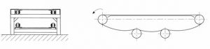
• the chain’s working mode must be perfectly defined, referring to the various possibilities explained above.
• the weights involved (including that of the chain, which must be estimated from the outset), friction of the chain and of the load being transported, lengths, angles, data concerning any curves, etc.

Calculate the forces exerted on the chain:

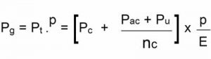
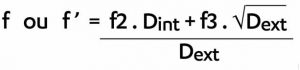
• the traction forces owing to the weights and friction (as well as to any curvature) cause traction constraints in the plates and shearing in the pins, as well as contact pressure between the pins and bushes).
• the normal forces (owing to the weights and any curvature) that cause contact pressure between the  rollers and the bushings on the one hand, and the supporting surface on the other hand.

Choose the chain according to its working mode and the result of the calculations according to one or more of the following criteria:

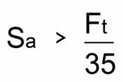
•the chain’s tensile strength,
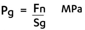
• the wear resistance of its hinges and rollers.

Do the calculations again, introducing the weight of the selected chain if this weight is significantly different from the weight estimated for the first calculations.
Decide on the technical details for making the installation, referring to the recommendations and  making sure that all the working conditions initially stipulated have not changed to such an extent they put the calculations into question.

Force calculations

GENERAL FORMULAS
Maximum traction force in Newtons (at the input to the drive wheel):

Maximum normal force in Newtons (resting on the guide surface):

Avec :

•  Pt and Pm : the total weights (in N) respectively supported by the taut strand and by the slack strand
•  f and f’ : the friction coefficients on the taut strand and on the slack strand
•  α : the angle (in degrees) of the chain’s average direction with respect to horizontal (positive value for the upwards movement)
Pg : maximum weight (in N) applied on the roller
Fp : catenary force (in N) on the slack strand if it is not supported, given by the  relationship below (for a center-to-center distance E and a deflection h):

Influence of curvature

As a usually satisfactory initial approximation, when the chain’s direction is inflected by an angle β (in radians) on a ramp with a friction coefficient f, you just have to make a correction to the forces using the formulas below.

Corrections :

– multiply Ft by eβf

– multiply Fn by: (1+e2βf-2eβf cosβ)0.5

Selection for tensile strength

This concerns a verification, because in conveyor installations it is only in exceptional cases where the chains are submitted to great continuous or jolting  forces that their failure by breaking must be feared before they become worn.

You must calculate a maximum force Ft on the chain using the relationships given in the previous chapter. This force must be corrected to take the operating conditions into account. For coefficient k, we have the following values:

moderate jolts ………………….. k = 1,2
violent jolts ……………………. k = 1,4
dragging ……………………………….. k = 1,4

You then check that the tensile strength Rr is higher than 5 times the corrected force Ftc. We call the safety coefficient Kg (here it is at least equal to 5).

Force calculations

For the lifetimes usually required in industrial applications (50,000 hours) and/or when the environment is aggressive (abrasive dust, for example), the origin of the risk of chain failure lies in the wear of the parts subject to friction, in particular the  pins on the bushes.

To avoid wear on the hinges (with abnormal lengthening of the chain impacting its functioning) and to prevent them from seizing  causing an increase in the required power, the contact pressure must be limited in the hinges.

Pressure in the articulations: Calculs des efforts, pression dans les articulations

► Bearing surface area (with a pin of diameter da and a bushing of length Id):    Sa = da.Id    mm2

Permissible pressure for normal operating time (chain length and speed) and maintenance (lubrication) conditions:

Pa   <   35 MPa


Choose a chain that has a bearing surface area at least equal to the value given by the relationship:Formule calculs d'efforts

Consult us for more severe operating conditions.

Selection for roller wear resistance

When the loads supported by the chain’s rollers (directly or otherwise) are great, it is their wear that risks limiting the chain’s service life.

The rollers support the normal component Fn (see calculation formula above) possibly corrected by the effects of a curve.

In order to determine the average value of Pg we use the weight calculation given below in the “Weights used in the formulas” section, referring these weights to the chain’s pitch p.


Déterminer Pg

nc = number of chains in parallel on the conveyor. But locally Pg may be significantly higher than the average value.

In addition to the weight of the chain and its accessories, there is the weight of the payload P.

► Payload applied directly to the articulation (hollow or extended pin as shown below) or applied to the plates (holed or bracket plates):

On consecutive links:

On an isolated link:

► Payload P with length L on a chain with pitch p:

► Bush/roller contact pressure:

Pression de contact douilles/galets

► Contact surface area in mm2  of a bush of external diameter dd and a roller of length Ig:   Sg  = dd . Ig  mm²

Permissible pressure for normal operating (chain length and speed) and maintenance (lubrication) conditions:

– For an untreated steel roller     Pg < 2 MPa
– For plastic wheels (POM):        Pg < 2,2 MPa
– For a treated steel roller:    Pg < 2,5 MPa
– For a carburized steel roller:     Pg < 3 MPa

Weights used in the formulas

The chain’s weight Pc (in N) which is deduced from its linear density Mc (in kg/m) given in the catalog, acceleration of gravity g (9,81 m/s) and from the length of the strand which can be considered to be equal to the center-to-center distance E (in mm)

Pc = Mc . g . E

► The weight of the accessories Pac (in N) not included in that of the chain can be deduced from their unit weight Pac (in N), their distance Iac (in m) and the length E of the strand:

Le poids Pac des accessoires (en N)

► The weight Pu of the load transported. Different possible cases:

 Distinct loads with unit weight Pu (in N) distance lu (in m) apart:

Continuous loads (loose or objects) with linear density Mu (in kg/m):

Distinct or continuous loads whose weight rate Q (in N/min) is known, or the number No of objects of weight Pu to be transported per minute at speed v (in m/mn):

If there are nc chains working in parallel:

Slack strand, Taut strand

• to be chosen directly in table 1 in the case of the chain sliding on its plates:

f  ou  f’  =   f1

• to be established according to the coefficients given in table 2 and the diameters of the parts in contact, in the case of the chain rolling on its rollers with an external diameter Dext and a bore Dint:

Frottement avec tableau 2

In the case of loose transport, it is the friction of the product transported in the chute that is relevant, that of the chain generally being negligible. Table 2 gives the density and friction coefficient of some materials generally  transported loose.

Table 1

Friction parameters Minimum:
smooth and lubricated surfaces
Maximum:
rough and dry surfaces
Plates sliding on a steel guide f1 = 0,08 f1 = 0,40
on a plastic guide f1 = 0,10 f1 = 040
Sliding between bush or roller f2 = 0,10 f2 = 0,20
Rolling of a roller on a steel guide f3 = 0,05 f3 = 0,10
on a plastic guide f3 = 0,07 f3 = 0,15

Table 2

Materials sliding down a steel chute Apparent density f
Clay 0.77 0.63
Asbestos 0.19 0.58
Limestone 1.00 0.47
Cement 0.94 0.54
Lime 1.53 0.46
Aluminum ore 0.83 0.55
Iron ore 2.99 0.47
Nickel ore 0.92 0.45
Lead ore 3.26 0.77
Zinc ore 1.93 0.79
Scrap metal – Swarf 0.54 0.73
Slag 0.90 0.48
Calcium carbonate 0.88 0.49
Ammonium chloride 0.67 0.79
Charcoal 0.44 0.41
Coal 0.30 0.53
Pinewood 0.70 0.41
Wood chips 0.36 0.74
Barley 0.39 0.71
Rice – wheat 0.77 0.40
Sugar 0.68 0.47
Polyethylene 0.34 0.52
Rubber powder 0.39 0.53
Chrome powder 1.14 0.51

Recommendations for designing the installation

Number of wheel teeth:
As conveyor chains usually have a relatively large pitch to allow the plates to receive the accessories, the designer should reduce the number of teeth on the wheels to limit their size. However, the polygonal effect becomes significant with fewer than 12 teeth and even above that value with high rotation speeds.
Furthermore, for a wheel that only has a small number of teeth and a large pitch, you must comply with the indications given in the catalog concerning the maximum hub diameter, to ensure it does not interfere with the plates.

Adjusting the center-to-center distance:

The center-to-center distance must be adjustable for several reasons:

•  to facilitate installation of the chain,
•  to ensure its maintenance and compensate for its stretching over time.

A play pick-up system must be provided, either with:

• a screw (figure opposite)
• springs
• counterweights
• cylinders

Caution: by principle, the chain functions without any tension in the slack strand, because the drive ensured by the wheels is positive. However, in certain special cases tension is required. The value of the tension force must not exceed 10% of the useful force in the chain or 1% of the tensile strength.

Supporting and guiding the strands

The taut strand – which usually carries the load – is supported as it slides or rolls over a guidance surface.
Do not forget to use shouldered rollers for large center-to-center distances and in the case of transversal forces.

The slack strand may be supported by sliding because it is loaded less, but roller bearings can also be used (if they exist) or a support provided by a series of idler wheels.  It is only possible not to provide support for small center-to-center distances, because the catenary effect becomes prohibitive for large center-to-center distances. In any event, the deflection must not exceed 0.4 % of the center-to-center distance. This condition may require a tension value that is too high if the strand is not supported.


Soutien et guidage des brins
The engagement of both of the chain’s strands on the wheel must be ensured with care: the guidance must be aligned perfectly with the teeth. Ensure that the end of the guide is rounded to facilitate the entry of the chain.

Wheel misalignment:

b1/2 : for lengths of less than 10m

b1 : internal width of the interior link

b1 : for lengths greater than 10m

Parallelism defect for the teeth planes: the wheels must be parallel (< 40′)
► Tolerance on the length of conveyor chainsbetween 0 and + 0.25 %
This tolerance must be lower if the two chains work in parallel and are joined by crosspieces or other accessories (indicate this in your order)

symbols, units and main formulas

symbols and units

 Description Symbol Unit
Acceleration of gravity (≅9,81) g m/s
 Angle with respect to horizontal  α  radian
 Chain inflection angle  β  radian
Overall friction coefficient: taut strand  f
Overall friction coefficient: slack strand  f’
Pin diameter  da  mm
 Bushing external diameter  dd  mm
Toothed wheel pitch diameter  Dp  mm
 Distance between accessories lac  m
Traction force  Ft  N
Normal force  Fn  N
Centrifugal force  Fp  N
Center-to-center distance  E  m
Slack strand deflection  h  mm
Bushing length  ld  mm
Roller length  lg  mm
 Chain linear density  Mc  kg/m
Continuous load linear density  Mu  kg/m
 Number of chains in parallel on the conveyor belt  nc
Chain pitch  p  mm
Weight of the chain  Pc  N
Weight of the accessories  Pac  N
Unit weight of the accessories  pac  N
Weight supported by a roller  Pg  N
Weight of the transported load  Pu  N
Total weight supported  by the taut strand Pt N
Total weight supported  by the slack strand Pm N
Pressure in the hinges pa MPa
Hinge surface area Sa mm²
Bush/roller surface area Sg mm²

main formulas

Maximum traction force:

Weight of a chain strand (taut or slack):

Weight of the accessories:

Weight of the taut strand:   

Weight of the slack strand:   

Pressure in the hinges:

examples of applications

THE CHAIN AND THE MATERIAL SLIDE IN THE CHUTE:
Maximum traction force:              Ft = Pt . f + Pm . f1     ou     Ft = (Pc . Pu) . f + Pc . f1

Where f: coefficient of the material transported in the chute & f1: sliding coefficient for the chain’s plates in the chute.

THE CHAINS ROLL, THE LOAD IS CARRIED:

►  Maximum traction force:  Formule effort de traction maximale

Where f and f’: the rolling coefficients which depend on the roller’s bore and external diameter.

The roller’s normal force is: Formule effort normal du galet