Like all chains, conveyor chains consist of articulations made of pins and bushes connected with plates. Their essential feature is that they can receive various means for fastening accessories suited to the conveyor method used and to the nature of the load to be moved. Their pitch, which is generally large, is not a unique characteristic and can be chosen from a large range of values.
Chain technique – Conveyor chain
The different types of conveyor chains
ISO standard conveyor chains
Basic chains
SEDIS chains comply with the ISO 1977 standard. This range is based on the minimum tensile strength, pitch, type of pin and roller and the specific features of the plates. These different characteristics enter into their designation.
– The minimum tensile strength goes from 20 to 900 kN, according to a series based on the preferred numbers
– These chains’ pins are usually solid, but they may also be hollow when they are intended for fastening accessories or spacers linking two chains working in parallel.
– The pitch must be chosen according to the utilization conditions, the type of product to be carried, the frequency of the accessories, the available space, etc. All the pitch values are also established according to preferred numbers, but not all of them can be made: refer to the table in Chapter 2 giving the preferred pitches. Pitches with intermediate values or pitches in inches can also be proposed.
These basic chains may be:
► with bushes: for low speeds (conveyor, feeder, scraper belts) and in certain precise cases where the chain’s accessories are the carriers, and here the chain serves essentially as the traction component.
► with small rollers: in elevators where the chain’s speed is higher and causes impacts at the moment of gear meshing. The rollers, made of quenched carburized steel or of steel that has received another treatment, protect the bushes and prevent tooth wear.
► with wheels (rollers with a diameter greater than the height of the plates): these rollers allow the chain to roll on a flat surface. The rollers may be plain or flanged to ensure lateral guidance. Plain and flanged rollers are made of treated steel.


► G attachments with one or more holes forming an attachment plane that is parallel to the plates.
► F attachments forming an attachment plane perpendicular to the plates.
► K attachments with one or more holes forming an attachment plane that is perpendicular to the plates with a choice of three different center-to-center values between the holes (K2 with a short, medium and long center-to-center distance), the width of the attachments varying accordingly.
These attachments can be made on the inner or outer links, on one or on both sides, according to a frequency and layout to be indicated in the order.
►Special attachments can be made to order, provided the quantities are sufficient.
Connecting links
There are three types of connecting link:
► with self-locking nuts: the two pins are riveted to a plate on one end, and the other end receives a connection plate immobilized by self-locking nuts.
► with cottered pins where the connecting plate is immobilized with cotter pins to facilitate removal. For some applications we can deliver chains with external links cotter pinned on one side.
► with cottered pins where the connecting plate is held by pins riveted both sides after assembly of the chain.

Designation
The ISO conveyor chains with solid pins are designated by the letter M. The chains with hollow pins are designated by the letters MC, and those with offset plates by the letters MD, followed by the following indications:
►their minimum tensile strength expressed as kN
►a letter indicating the type of chain:
•B for bush chains
•S for small roller chains
•P for treated plain wheel chains
•F for treated flanged wheel chains
►a number corresponding to their pitch (in mm)
Example: Chain M 160-F-200 is a standard conveyor chain with solid pins, with a minimum tensile strength of 160 kN, flanged wheels and a pitch of 200mm.
The drilled plates must be clearly defined in the order: inner, outer, number of holes, and frequency of these plates on the chain.
BS standard conveyor chains
These chains are designed according to the British Standard (BS 4116) in terms of tensile strength and dimensions.
Their designation is similar to that of the ISO conveyor range. Each chain has the following attachments
Drilled plates, offset plates, K attachments, scrapers and hollow pins
• BS chains – Factory Standard: the dimensions and pitches are metric
• BS chains – British Standard: the dimensions and pitches are in imperial values
French series conveyor chains
The particularity of French series chains lies in their articulation (pin/bush) which enables the chains to withstand the jolts and impacts that may sometimes be inevitable. There are three series of chains (light, normal and high strength).
The high strength chains (treated plates) are used for difficult applications (great forces, transporting abrasive products, etc.)
The French series conveyor chain have the following accessories: K, G and F attachments.
Block chains
lock chains have a high tensile strength for small dimensions. They are used for conveyor heavy, abrasive objects or when there will be serious impacts (draw benches for example).
In order to lengthen the chain’s service life (better wear resistance), the blocks are sometimes collared.

Galle chains
Galle chains consist of straight or waisted links (or plates) and shouldered pins. The pin shoulders maintain the spacing between the plates and allow meshing on the gear. The chains are single, double or triple link depending on the desired tensile strength.
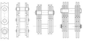
Galle chains can be used to transmit forces varying between some hundreds of Newtons and several thousand kilo Newtons, as for the speed, it must not exceed 20m/mn.
Galle chains are used for low-speed transmissions (draw benches) or to make back-and-forth movements (goods-lifts, sluice gates, etc.).
Wheels & Sprockets
The wheels used with conveyor chains are made of precision-welded steel or cast iron.
Normally the teeth are rough cast or oxygen-cut but, on request, they can be delivered with cut teeth, which is essential when sleeve chains are used.
The hubs are offset with respect to the tooth plane except where a symmetrical hub is especially specified. The wheels can be supplied bored and grooved. In the case of sloping keys on an offset hub, the key slot is on the tooth side, unless otherwise specified.
Number of teeth and dimensions:
The dimensional data tables give the commonly used number of teeth. But on request we can supply wheels with a different number of teeth. The tables also give the main wheel dimensions for the most common pitch values:

• Pitch diameter Dp and External diameter De,
• Hub diameter Dm and width L,
• Dimension a giving the position of the tooth plane on offset hub wheels,
• Width of the normal teeth and for shouldered rollers
• Bore minimum diameter d and maximum diameter D
• Approximate weight